
- #ARDUINO ANALOGWRITE SET TO 0 HOW TO#
- #ARDUINO ANALOGWRITE SET TO 0 FULL#
- #ARDUINO ANALOGWRITE SET TO 0 CODE#
Why is the Arduino trying to fry itself by supplying more current to the device than it's supposed to? What kind of transistor are you telling me to buy - 12V 40 mA and 5 V mA? I am literally following setup guides that show this exact same wiring diagram and code. Modulating voltage should modulate the speed (and therefore volume of air) of the fan?

The tiny fan I'm using has 3 pins, one of which is just a useless signal pin that just notifies a computer that it's working - the third pin (signal) on the fan is not connected to anything.

It's not a 12V fan, it's a single 5V fan? If you got a computer fan with PWM speed control (the 4-pin ones) the extra pin is for PWM speed control, and you can put 12v across the fan and use 5v PWM on the PWM speed control pin, and then you don't need additional components.
#ARDUINO ANALOGWRITE SET TO 0 FULL#
If you used an N-channel MOSFET on the low side of the fan, and put the high side onto +12v, you could run the fan at a full 12v (I don't think all of those fans will even spin at 5v) You need to use a transistor to switch high current loads. My problem is however with analogWrite () function which seems to set the PWM to HIGH whenever you write analogWrite (PWM, 255) Yes it does, it is designed to do this because it is designed to use an 8 bit timer. Stop doing that before you burn out the pin driver. Oh yeah, there's no way you can power a 12v fan that typically uses that type of connector via an Arduino I/O pin, even with 5v, it would draw far too much current (which is what is happening, that's why the pin isn't able to provide a whole 5v).
#ARDUINO ANALOGWRITE SET TO 0 CODE#
put your main code here, to run repeatedly:ĪnalogWrite(fan1Pin, 250) //Should be linear relation between 0-5V and 0-255 analog output.Ĭorrection: Vin is only supplying 4V when it's supposed to be supplying 12V. put your setup code here, to run once: This pin is PWM enabled for analog output 0-255 Sketch: const int fan1Pin = 5 //Output pin for the fan. I set the pin as INPUT after tone() to eliminate the noise. If you use a speaker or passive piezo with esp8266 you can expect noise generated by WiFi operations. It measures 3.23V for DC and square wave is just -000. Your analogWrite(255) is PWM at 1/4 of full on, because max analogWrite value on esp8266 is at default 1023. The analogWrite() function takes two arguments: the Arduino pin number (9 in.
#ARDUINO ANALOGWRITE SET TO 0 HOW TO#
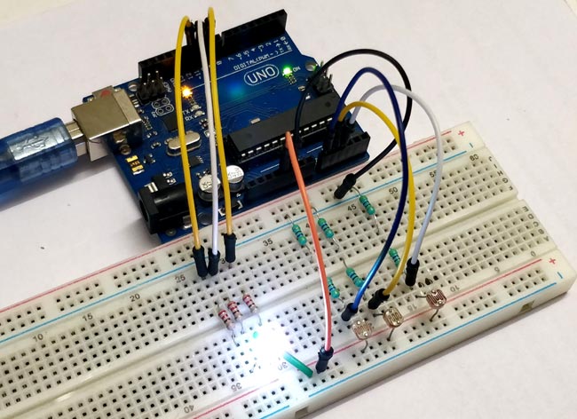
I am placing it at the exposed yellow wire and the black wire at the base of the fan. You already learned how to use Arduinos digital i/o pins to send HIGH and. I'm using a multimeter set to measure DC voltage and the square wave. Pin 5 (on the PWM side) is an output going to the red (+) terminal on the fan, black (-) terminal is hooked up to breadboard bar wired to the arduino's ground. There's a 12V power supply to the board in addition to USB. Need to see your wiring diagram - have you other stuff connected ? How are you measuring the voltage ? And your sketch - something is wrong but it’s not obviousĪttached picture of wiring setup.


 0 kommentar(er)
